I2C interface
Raspberry Pi SPI and I2C Tutorial
Continuous deployment (Russian) Непрерывная кросс компиляция на Raspberry PI
Controlling motors
Brushless motor
Control brushless motor with ESC. Without additional controllers
With PCA9685 PWM Board (stackexchange thread)
Controlling multiple servos
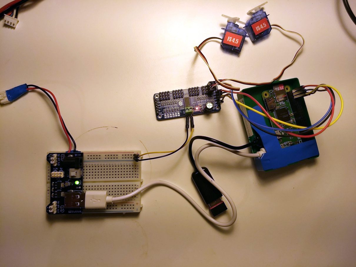
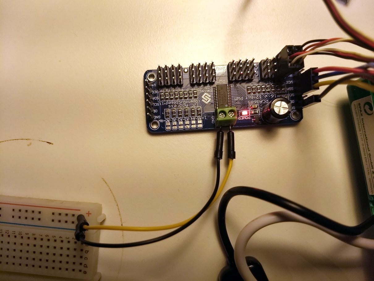
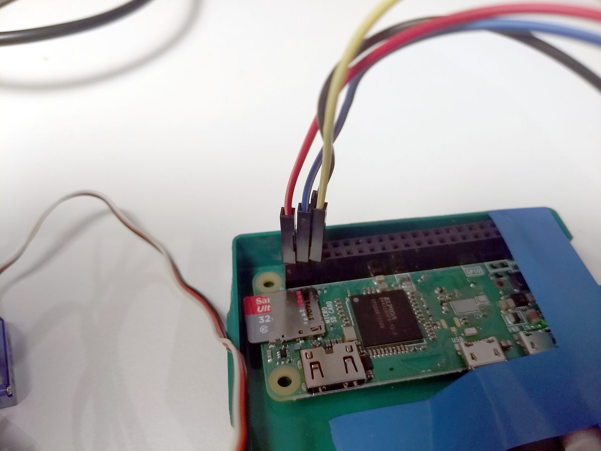
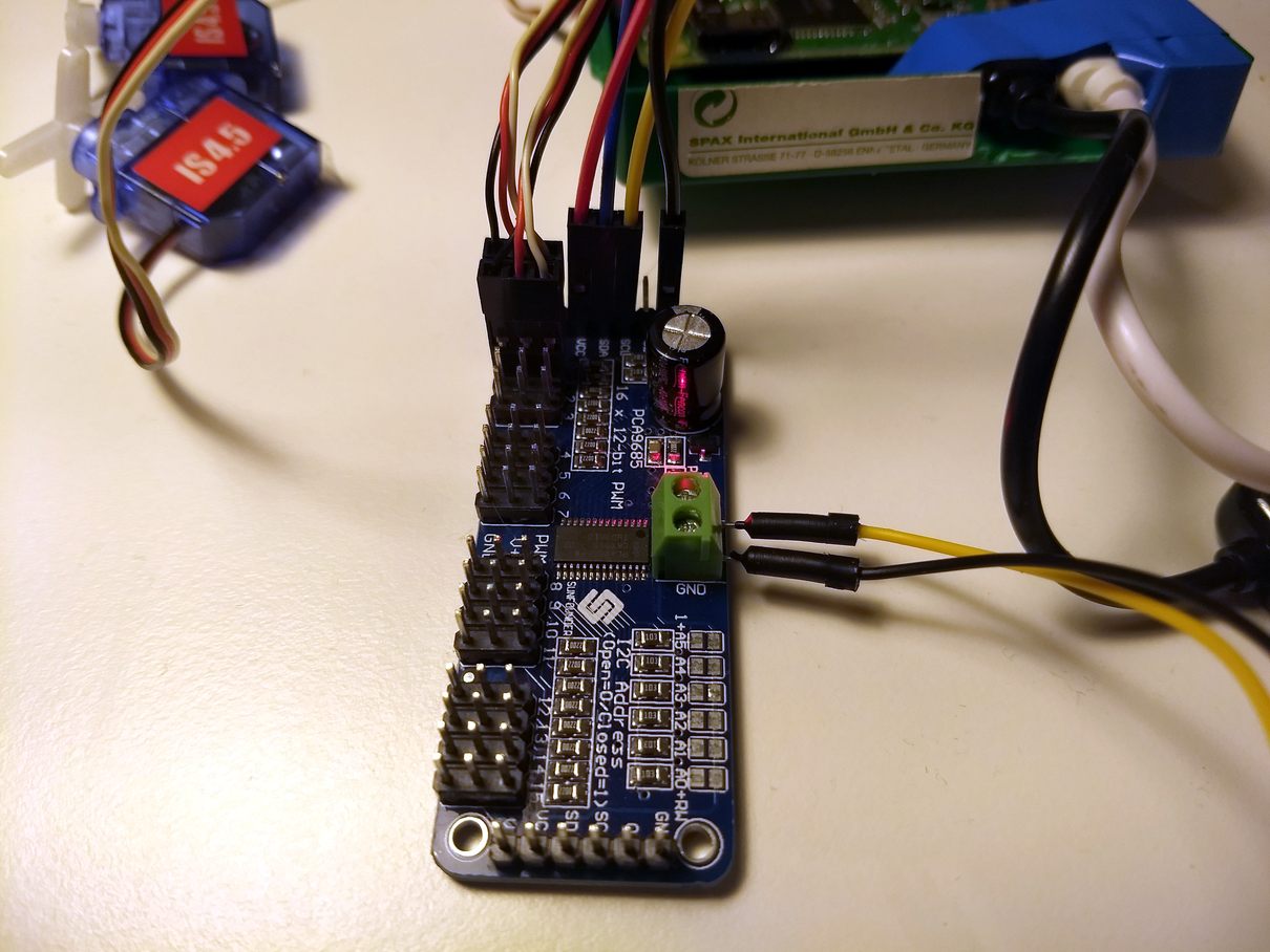
To control multiple servos you can use PCA9685 controller. Connection is shown below. It’s better to connect VCC of the controller (red wire) to +5V or raspberry or to external power supply.
Now installing the diagnostic tool and running:
sudo apt-get install -y i2c-tools
sudo i2cdetect -y 1
     0  1  2  3  4  5  6  7  8  9  a  b  c  d  e  f
00:          -- -- -- -- -- -- -- -- -- -- -- -- --
10: -- -- -- -- -- -- -- -- -- -- -- -- -- -- -- --
20: -- -- -- -- -- -- -- -- -- -- -- -- -- -- -- --
30: -- -- -- -- -- -- -- -- -- -- -- -- -- -- -- --
40: 40 -- -- -- -- -- -- -- -- -- -- -- -- -- -- --
50: -- -- -- -- -- -- -- -- -- -- -- -- -- -- -- --
60: -- -- -- -- -- -- -- -- -- -- -- -- -- -- -- --
70: 70 -- -- -- -- -- -- --
Now we can install library:
pip install Adafruit_PCA9685
and run a simple program:
| |
running:
python sample.py
To control more than 16 servose one can chain multiple drivers. See Chaining Drivers section for details. Some soldering is required to assign a unique address for each driver.
See alow:
- datasheet
- Adafruit 16 Channel Servo Driver with Raspberry Pi Created by Kevin Townsend. pdf. (pca-9685)
- troubleshooting
- Controlling one servo. No additional controllers needed
Stepper motors / DC (brushed) motors
[Raspberry] Stepper and dc motor using specializer HAT
Based on PC9865 PWM and TB6612 chipset. 1.2A per channel current capability (20ms long bursts of 3A peak)
[Arduino] With adafruit motor schield v1
Based on 74HC595N Serial to parallel output latch and L293D driver. 0.6A per bridge (1.2A peak) with thermal shutdown protection, 4.5V to 25V.
Library for motor control
See also about SN74HC595 shift register
[Arduino] With adafruit motor shield v2
Based on PCA9685 and TB6612 MOSFET drivers with 1.2A per channel current capability ( up to 3A peak for approx 20ms at a time)
[Raspberry] Drive a DC motor forward and in reverse with variable speed (with l293d, adafruit lesson 9)
[Micropython board] Control dc motor with pca9685
[Raspberry] Video with just simple transistor scheme and with L293D controller
[Raspberry] using L293D and 4N35 opto isolator
[Arduino] 1 bidirectional DC motor using small DRV8871 motor driver
Up to 45V and 3.6A of motor control
It is possible to have frequency controlled dc driver connected through Adafruit 16 Channel Servo Driver. See post. controller, ~100 Euro, powerfull
[Arduino] using drv8833 driver,
Using transistors: (1)[http://electronics.stackexchange.com/questions/7235/motor-driver-using-only-a-2n2222-transistor], very weak
Connecting via ssh:
ssh -Y user@raspberrypi-url
Access rasbberry Pi without monitor and ethernet
Assuming we have an operating system (raspbian) installed.
Plug the SD-card into a computer.
Automatic connection to wifi. Edit
/etc/wpa_supplicant/wpa_supplicant.confand add the following lines:
network={
    ssid="my-network-name"
    psk="my-network-pass"
}
In the end the file should look like this:
country=GB
ctrl_interface=DIR=/var/run/wpa_supplicant GROUP=netdev
update_config=1

network={
    ssid="my-network-name"
    psk="my-network-pass"
}
country field is essential. Wifi wont work without it. In the log you will see raspberrypi systemd[1]: Started Disable WiFi if country not set.
If you need to support multiple wifi connections use id_str field:
network={
    ssid="my-network-name"
    psk="my-network-pass"
    id_str="net1"
}

network={
    ssid="another-network"
    psk="another pass"
    id_str="net2"
}
Enable SSH access. Create an empty file
sshin/boot/.Plug the card back into your raspberry, turn on.
Now you can connect to raspberry via ssh:
ssh pi@raspberrypi
or
ssh pi@<IP-OF-YOUR-RASPBERRY>
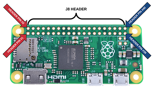
Reading input (button) from GPIO
RaspberryPi Zero pins Layout
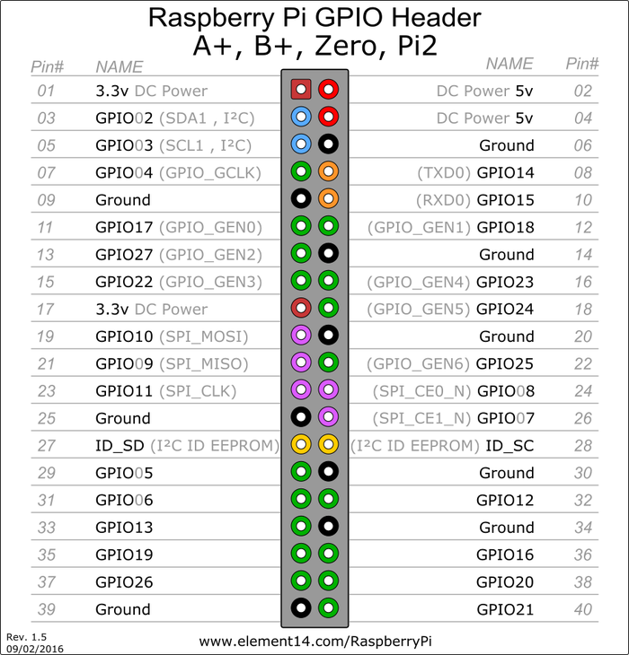
Interactive website for pinout of Raspberry Pi for different interfaces Pinout
Donkey car
Requirements for running donkey car:
sudo apt install -y libatlas-base-dev libopenjp2-7-dev libtiff5-dev libhdf5-dev